

In many cases, absolute rotary encoders are exposed to strong mechanical stress, electrical and magnetic fields, which affect the place where they are used. In order to counteract dirt, dust and liquids in an industrial environment, special design measures are therefore necessary.
Our absolute rotary encoders are mechanically robust according to the latest technical know-how, and the electronics are designed to be as compact as possible.
A main focus of the resistance to interference of our encoders is the data transmission from the rotary encoder to the control system.
The control system must be able to read the rotary encoder's measurement data without errors. Under no circumstances may undefined data be transmitted, e.g. at the step change point.
The design described here for synchronous serial data transmission for absolute rotary encoders differs from the parallel and asynchronous serial transmission types essentially by:

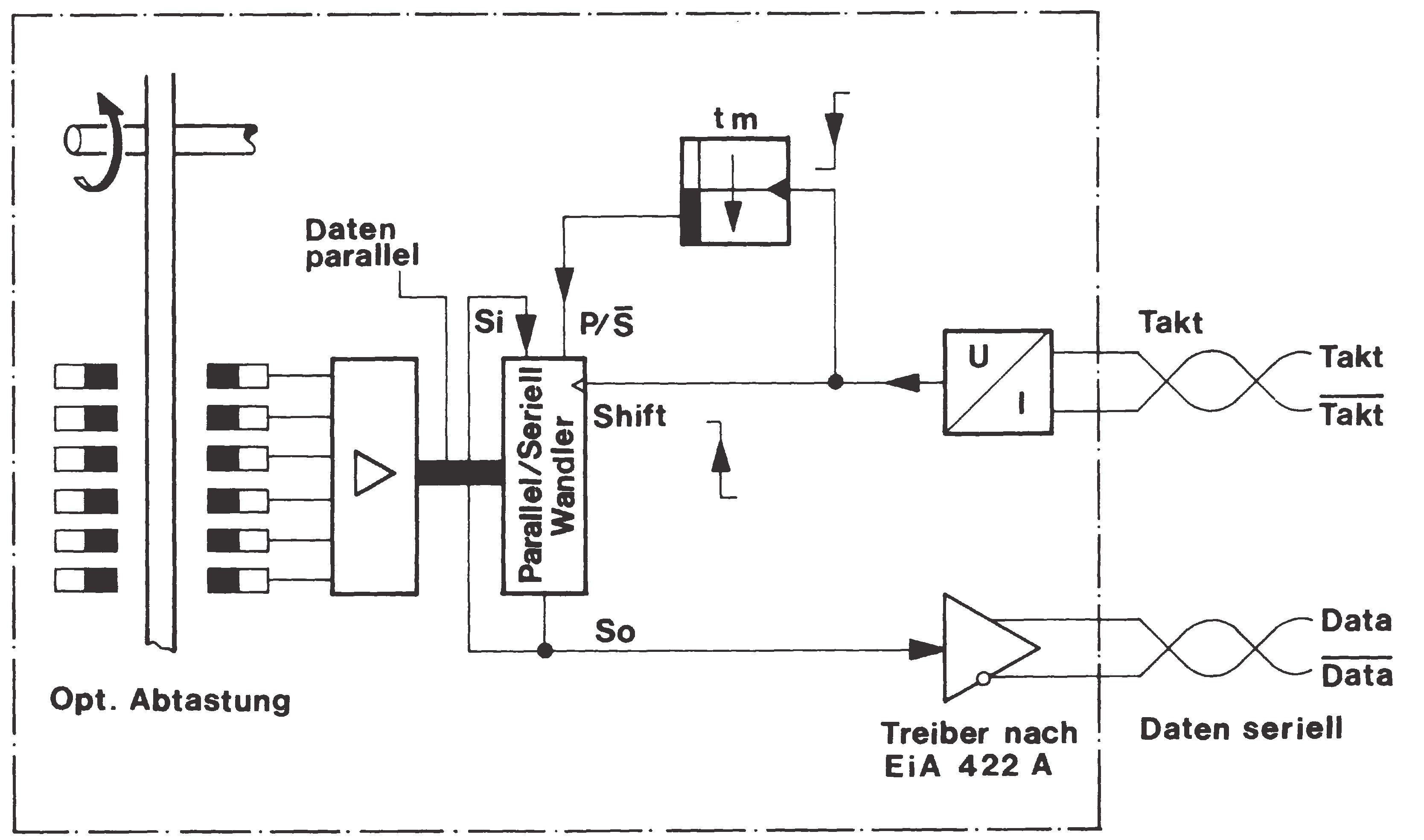
In order to transmit the data correctly, it is necessary to apply a defined number of pulses (clock pulse bursts) to the input of the absolute rotary encoder. Then a pause time (TP) must be observed. As long as there is no clock pulse signal on the rotary encoder, the parallel / serial shift register inside the encoder will be switched to parallel. The data are transmitted continuously and record the position of the rotary encoder shaft.
As soon as there is a cluster of clock pulses at the clock pulse input again, the current angle data will be saved. When the clock pulse signal changes from high to low for the first time, the retriggerable monoflop (monostable circuit) in the rotary encoder is activated, and the monoflop time tm must be greater than the time period T of the clock pulse signal. The output of the monoflop controls the parallel / serial register via the P/S (parallel / serial) connector.
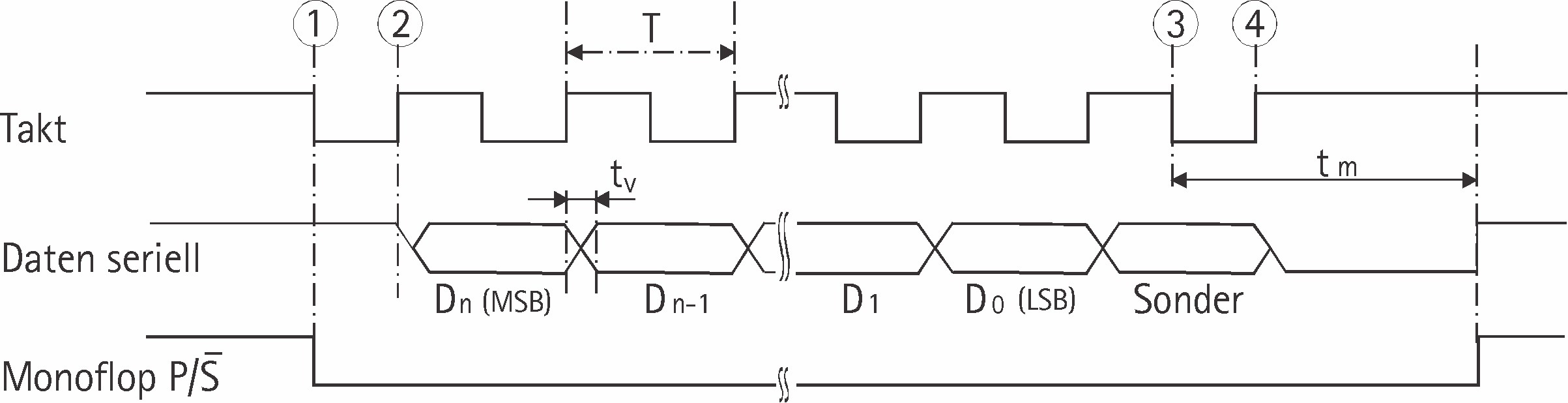
T = period of the clock pulse signal
tm = monoflop time
tm between 10 μs and 30 μs
tv = 100 nanoseconds
The number of clock pulses required for data transmission is independent of the resolution of the absolute rotary encoder.
The pulse cycle can be interrupted at any point or continued for multiple queries in the ring register mode.
When the clock pulse signal changes from low to high (2) for the first time, the most significant bit (MSB) of the angle data is applied to the serial data output of the rotary encoder.
With each further rising edge, the next lower bit is shifted to the data output.
After the transmission of the least significant bit (LSB), depending on the configuration, the alarm bit or other special bits are transmitted.
The data line then switches to low (3) until the monoflop time tm has elapsed. A further data transmission can only be started when the data line switches to high (4) again. If the clock pulse change at point (3) is not interrupted, the ring register operation will automatically be activated. This means that the data stored at the first clock pulse change (1) is fed back to the serial input S1 via the connection S0. As long as the clock pulse at (3) is not interrupted, the data can be read out as often as required (multiple data transmission).
The maximum data transmission rate depends on the cable length.
| Power and cable length | clock pulse rate |
| < 50 m | < 400 kHz |
| < 100 m | < 300 kHz |
| < 200 m | < 200 kHz |
| < 400 m | < 100 kHz |