
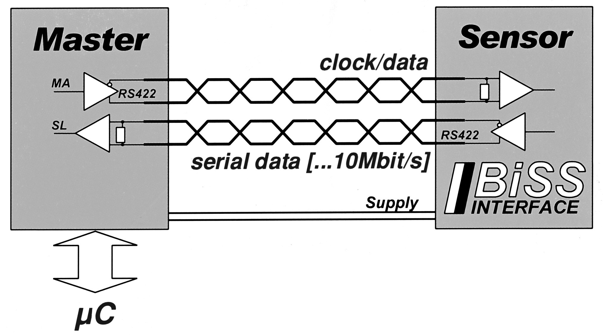
The bi-directional digital sensor interface BiSS ensures the communication between the position transmitter and the measuring device or drive control and simultaneously transmits measured values from up to 8 sensors if required. For 1 to 8 connected devices, the interface master supplies the clock pulse signal for the simultaneous acquisition of all the position data and for the subsequent synchronous serial data transmission.
Only four unidirectional RS422 data lines are required; the minimal slave electronics are located directly in the sensor's integrated circuits (ICs). If the interface master sends the clock pulse on the master line MA, the slave electronics will respond directly on the return line SL with the detected position data. Commands or parameters can be exchanged via pulse width modulation (PWM) clock pulses, but these are not required to start the bi-directional serial synchronous (BiSS) protocol.
With each data cycle, the master system learns and compensates for the signal transmission time, thereby enabling clock pulse rates of up to 10 Mbit / second even for cable lengths of 100 metres. Changing cable conditions, e.g. due to movements caused by towing forces, are corrected. The synchronisation accuracy between several transmitters on different axes is within 1 microsecond, and the master system also records the previous signal transmission times for the control system to read and enables further optimisation.
The bidirectional BiSS protocol classifies each connected device for different types of data: Sensor data, multi-cycle data and register data. These types of data sensors are designed differently in their ease of access and transmission performance in order to cover a large number of sensor applications. Bidirectional parameter communications for device configuration, possibly also for so-called original equipment (OEM) parameters, are usually recorded in the register data area.
Slowly changing data such as revolution counting or engine temperature are recorded in the multi-cycle data area, and rapidly changing angle data are recorded in the sensor data area. This means that controller cycle times of less than 10 μs are also no problem for data strings up to 64 bits. There is enough space for redundant systems and it is usually used for a CRC implementation (Cyclic Redundancy Check). Only framed by a start and a stop bit, the sensor data are transmitted with the best possible user data rate; a single multi-cycle data bit is optional. Also recorded when triggered, the multi-cycle data bits form a second in-band protocol and help to reduce the volume of sensor data required - permanent position and operation monitoring of the drive is possible without disturbing the controller cycle.
Specific device developments by individual users are not restricted or made unnecessarily expensive by the need for compatibility with other BiSS products. A bidirectional BiSS connected device is described with only a few parameters, a device description file in XML format supplied with it simplifies the commissioning of the control system. Overview: Absolute encoder (value transmitter): Open, digital sensor interface (BiSS) with synchronous serial transmission (SSI) INTERBUS CANopen DeviceNet Profibus-DP