Examples of flanges
Overview of flanges for
Rotary encoders with a clamping flange
The rotary encoders with a clamping flange offer the following fitting options:
- using various flange adapters (see accessories)
- the clamping flange itself
- the fastening threads on the front
- or using a mounting bracket (see accessories).
The rotary encoder housing is centered on the clamping flange.
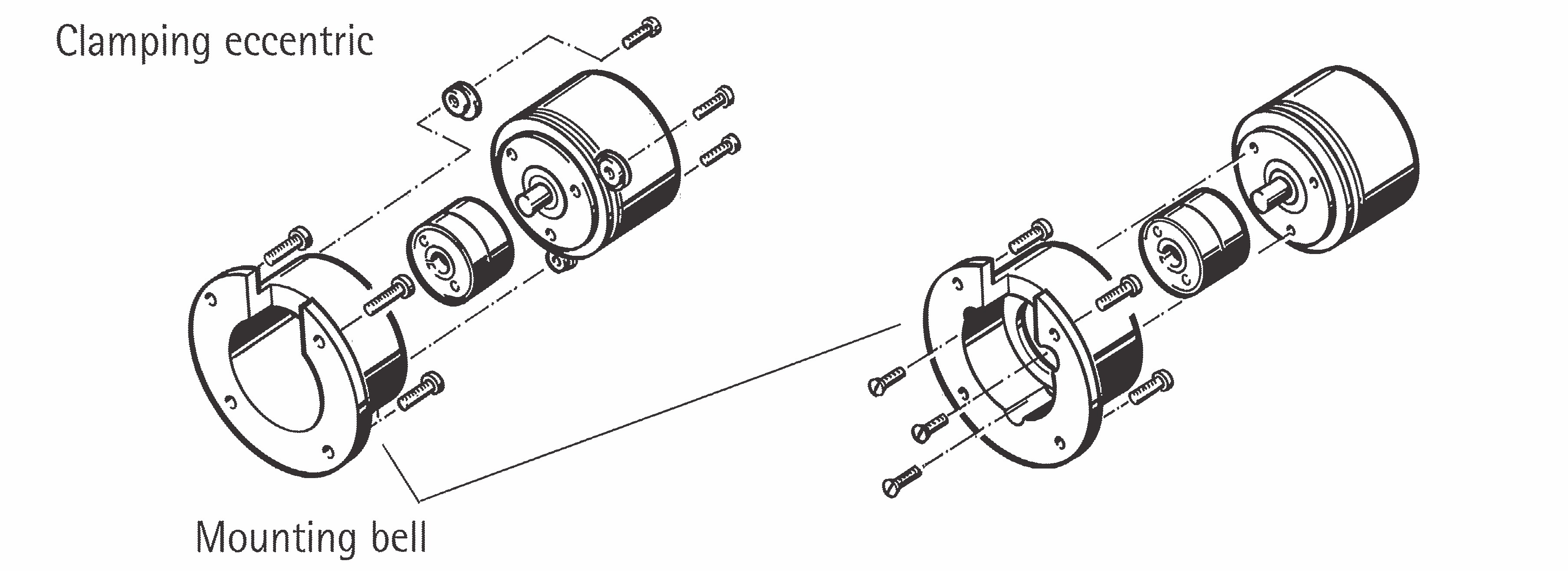
Rotary encoders with a synchronous flange
Rotary encoders with a synchro flange offer two mounting options:
- using the synchro flange and three eccentric fastening elements (see accessories)
- or using the fastening threads on the front.
The rotary encoder is centered using the centering collar on the flange.
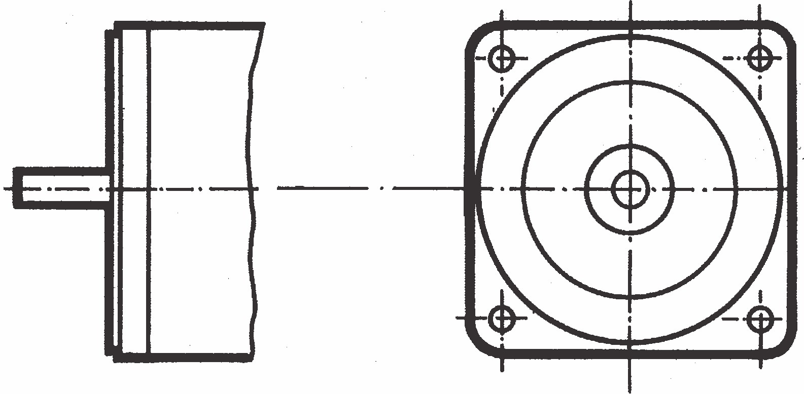
Rotary encoders with a square flange
Rotary encoders with a square flange offer two mounting options:
- using the continuous fastening thread for front or rear wall mounting
- or using a fastening bracket.
The rotary encoder is centered using the centering collar on the flange.
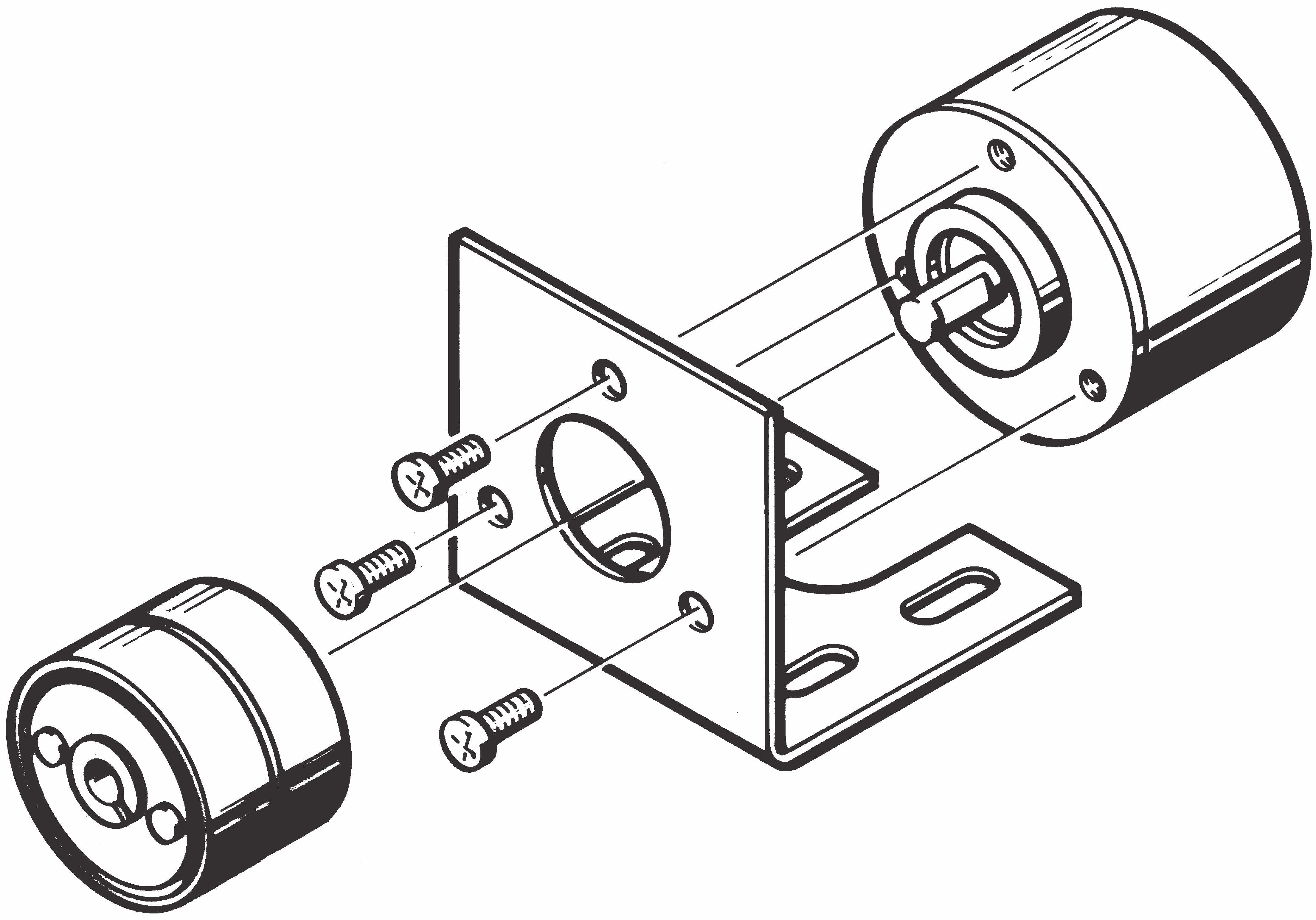
Rotary encoders with a round flange
Rotary encoders with a round flange offer two mounting options:
- using the fastening thread on the front side
- or using a fastening bracket.
The rotary encoder is centered using the centering collar on the flange.
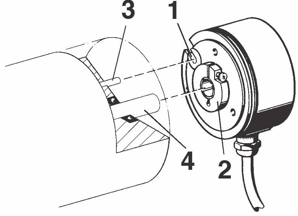
Rotary encoders with a hollow shaft (RI 58-D / G)
Fitting the variant F or D (clamping shaft)
- torque spring
- clamping ring with a Phillips screw (with cross-shaped grooves)
- cylinder pin and
- drive shaft
Fitting the variant E (end shaft)
- torque spring
- O-Ring
- cylinder pin
- drive shaft with threaded drilled hole
- M4-size screw, with a spring washer and
- cover cap
Rotary encoders with a hollow shaft (RI76)
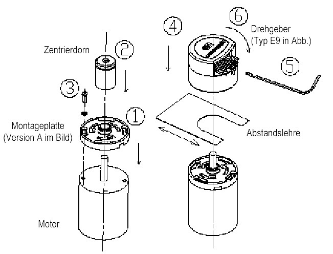
Motor rotary encoder with a hollow shaft (E9)
- Place the mounting plate on the motor end shield (bearing plate).
- Push the centering pin through the motor shaft and use it to centre the mounting plate.
- Screw the mounting plate tight and remove the centering pin.
- Place the rotary encoder on the mounting plate without securing it in place. The locking lugs must be inserted into the openings in the base plate. Insert the distance gauge from the side opposite the connector plug between the base plate and the rotary encoder.
- Press the code disk towards the motor and at the same time tighten the grub screw in the encoder shaft.
- Engage the rotary encoder housing by turning it clockwise (bayonet lock).
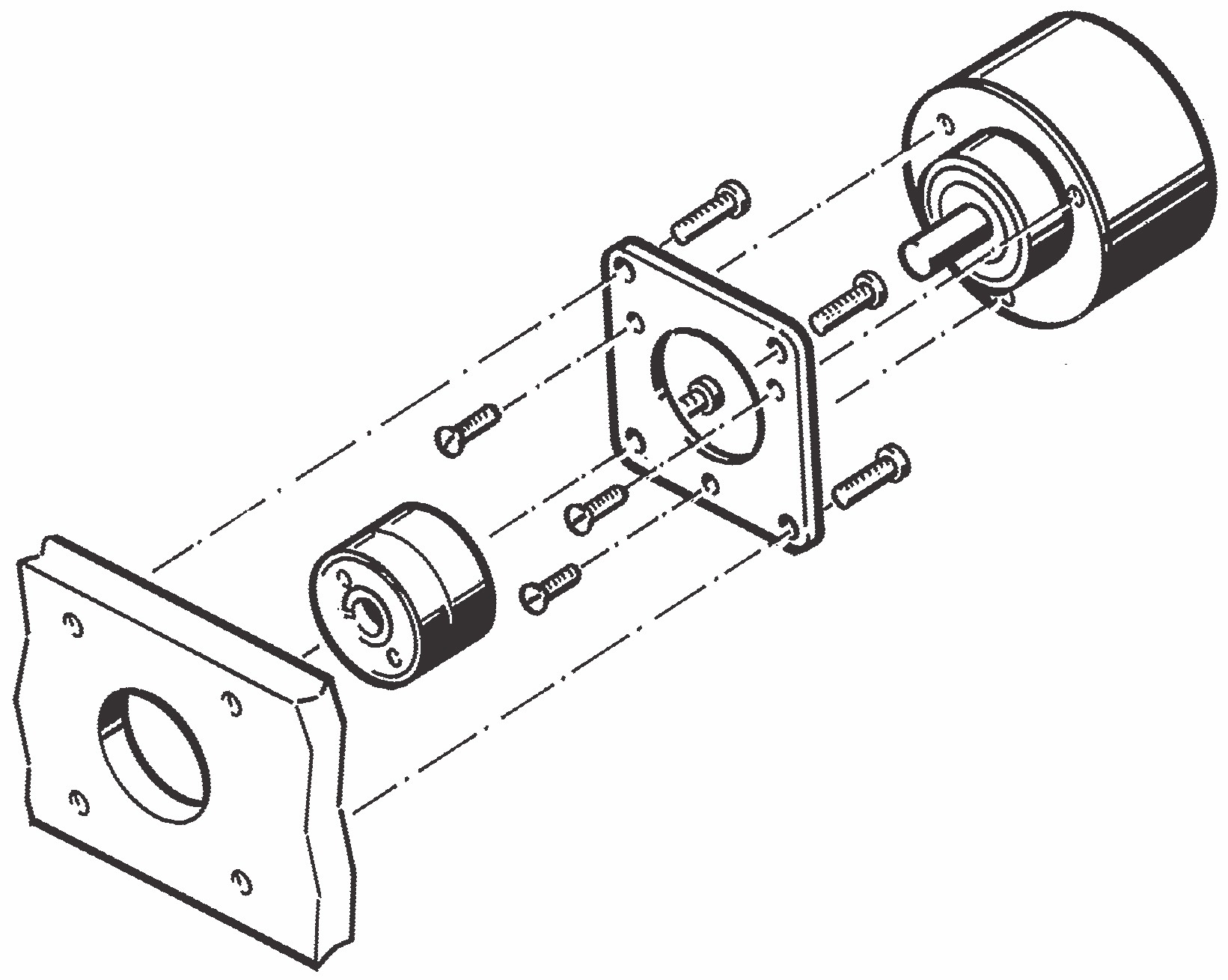
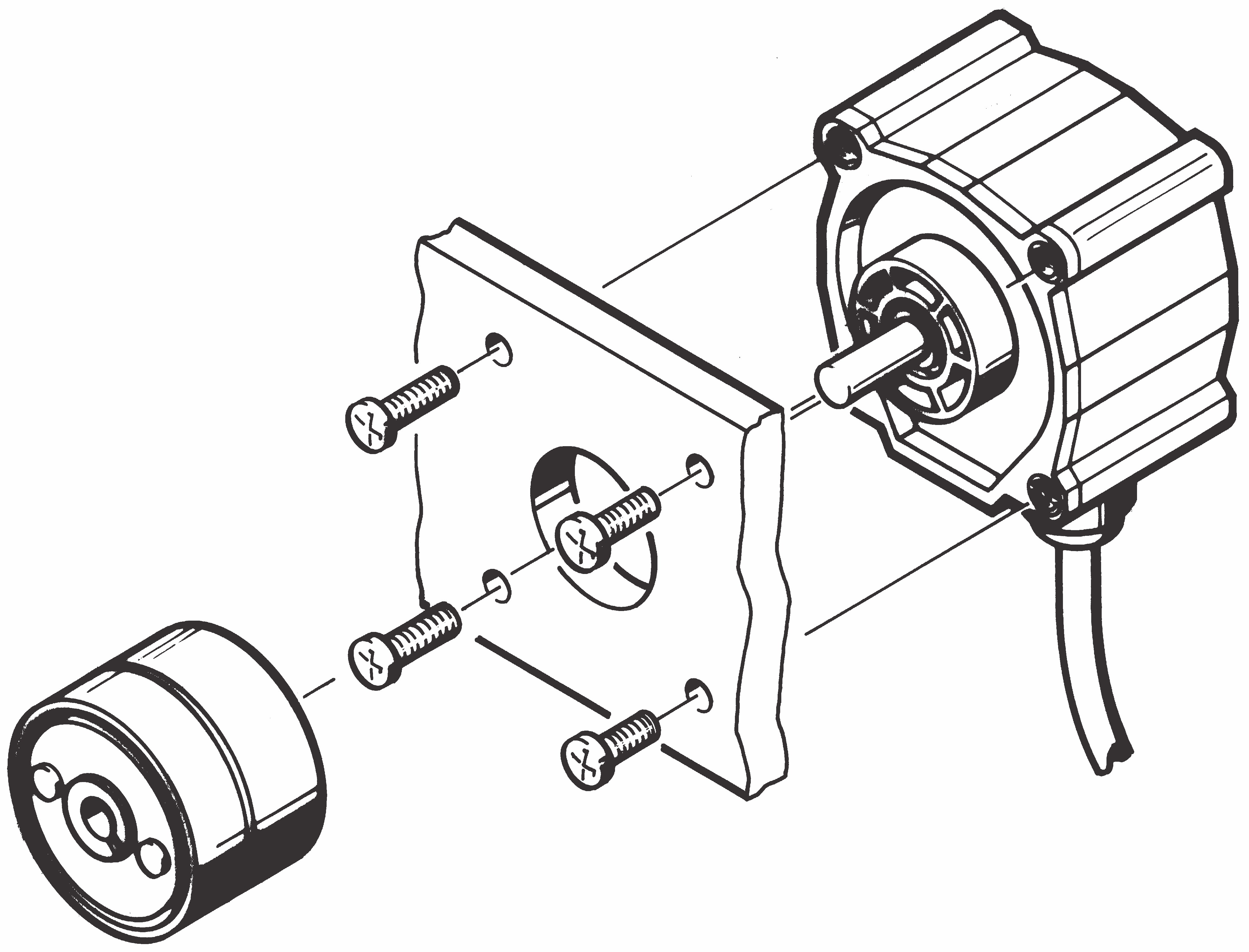
Rotary encoders with a solid shaft
The shaft-side coupling of the rotary encoders with a solid shaft is secured with a coupling.
The coupling compensates for axial movements and misalignments between the rotary encoder and the drive shaft, thereby avoiding excessive bearing loads on the rotary encoder shaft.