
The AC 58 is an absolute rotary encoder (encoder, angle encoder), which in the version described here sends its current position to another device connected to the bus via the transmission medium of a CAN bus (physically: a twisted and shielded 2-wire cable).
The CAN (Controller Area Network) serial bus system, originally developed by Bosch / Intel for automotive applications, is becoming increasingly used in industrial automation technology. It is multi-master capable, i.e. several devices connected to the CAN bus can send signals to the bus at the same time. The message with the higher priority (determined by the identifier) will be transmitted first without any time loss.
The data transfer is regulated by the priority of the messages. With the CAN bus, there are no addresses for connected devices or systems but only message identifiers. The messages sent can be received by all the connected devices at the same time (a broadcast system).
Using acceptance filtering, the connected devices will only accept the messages intended for them. The criterion for these decisions is the identifier which is transmitted with each message. The bus connection is internationally standardised according to ISQ-DIS 11898 (CAN High Speed) and allows data transmission rates up to 1 Mbit per second.
The most outstanding feature of the CAN bus protocol is its high level of transmission security (Hamming distance = 6). The Intel 82527 CAN controller we use is suitable for both basic and full CAN systems and supports the CAN specification 2.0 Part B (standard protocol with 11-bit identifier and extended protocol with 29-bit identifier).
So far, only 11-bit identifiers have been used with CANopen.
In systems in which the position of a drive or another machine part must be recorded and reported to a control system, this task can be carried out by an AC 58 encoder. In this way, positioning tasks can be solved, for example, in cases where the feedback on the current drive position is reported by an AC58 encoder to the positioning unit via the CAN bus.
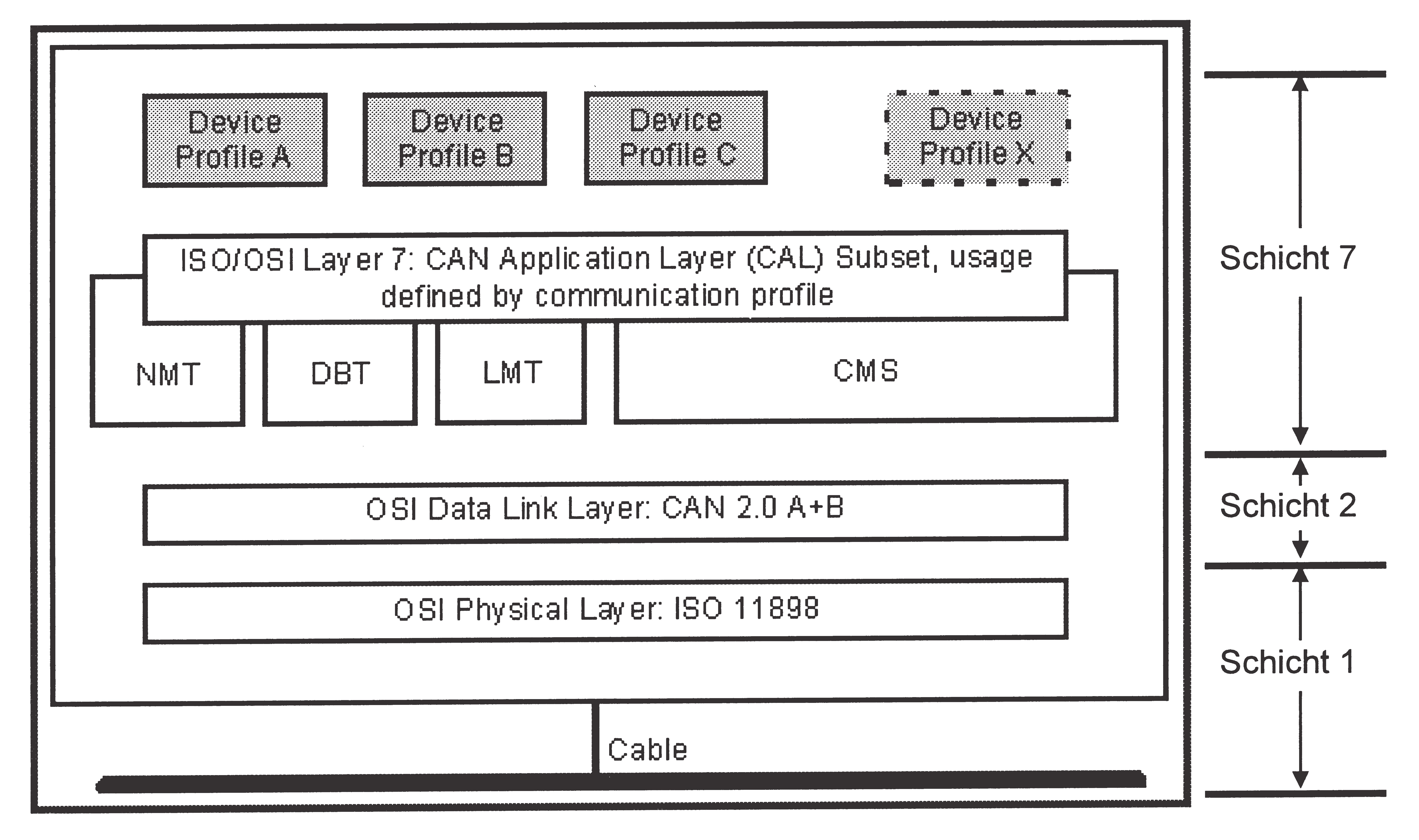
Layer 1 (Physical Layer): ISO-DIS 11898 (CAN High Speed)
Layer 2 (Data Link Layer): ISO-DIS 11898 (CAN High Speed)
Layer 7 (Application Layer): CiA DS 301 (CAN in Automation Draft Standard, CANopen CAL-based Communication Profile) + device profiles, CiA DS 4xx (CANopen Device Profile for xx)
Profiles already exist for the following devices:
About 2½ years after the adoption of the CAN Application Layer (CAL) by CAN in Automation (CiA), the association of users and manufacturers of CAN products, it became possible to develop open systems using CANopen and the relevant device profiles. CANopen was developed under the technical direction of the Steinbeis Transfer Center for Automation (STA Reutlingen, Germany) based on the layer 7 specifications for the CAL application layer. Compared to the CAL layer, CANopen only contains the functions suitable for this application. CANopen is therefore a subset of the CAL layer optimised for the specific application and it therefore enables a simplified system design and simplified devices to be used. CANopen is optimised for fast data exchange in real-time systems and is standardised for various device profiles.
The CAN in Automation (CiA) manufacturer and user association is responsible for creating and standardising the relevant profiles.
The AC 58 encoder with CANopen fulfils the requirements specified in the communications profile (CiA DS 301) and in the device profile for encoders (CiA DSP 406).
CANopen enables
CANopen uses four communication objects
(COB) with different features:
All the device parameters are filed or stored in an object directory. This object directory contains the description, data type and structure of the parameters and the addresses (index). The directory is divided into a communications section and a device profile section, as well as a manufacturer-specific section.
This profile gives a manufacturer-independent and binding definition of the interface for rotary encoders. The profile defines which CANopen functions are used and how they are to be used. This standard enables an open and manufacturer-independent bus system to be developed.
The device profile is divided into two object classes:
Class C2 devices can therefore carry out all the C1 and C2 mandatory functions, as well as other optional functions used by different manufacturers. An address range is also defined in the pNODE NUMBERrofile, and special functions for specific manufacturers can be assigned to these addresses.
With CANopen, data are transmitted using two different types of communication (COB = Communication Objects) with different features:
The priority of the message objects is determined by the COB identifier.
The process data objects (PDO) are used for the highly dynamic exchange of real-time data (e.g. encoder positions) with a maximum length of 8 bytes. These data are transmitted with high priority (low COB identifier). PDOs are broadcast messages and make their real-time data available to all the required recipients at the same time. The service data objects (SDO) form the communications channel for the transmission of device parameters (e.g. programming the encoder resolution). Since these parameters are not transmitted cyclically (e.g. only once when the network is started up), the SDO objects have a low priority (high COB identifier).
To simplify the management of the identifiers, CANopen uses the “Predefined Master / Slave Connection Set”. All these identifiers are defined with standard values in the object directory. However, these identifiers may be changed customer specific via SDO access!
The 11 bit identifier consists of a 4 bit function code and a 7 bit node number.
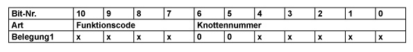
1 x = binary value freely selectable (0 or 1); 0 = value 0 fixed
The higher the value of the COB identifier, the lower its priority!
The 7-bit node number is set in hardware via 5 DIP switches on the back of the encoder.